Canalblog
Suivre ce blog Administration + Créer mon blog

Open Tuts

16 octobre 2009

Tutoriel GIMP: Fond à rayures

tut_grad5

Ce tutoriel va montrer comment créer rapidement des rayures sur une image ( comme par exemple, l'image à droite ici, avec les fines rayures diagonales).

La plupart des tutoriels existants nécéssitent l'utilisation d'un motif (pattern) à rayures, mais ici, nous allons utiliser des dégradés.
Cette méthode permet de créer rapidement des rayures de tout angle et toute largeur.

L'inconvénient est que ces rayures ne vont marcher que sur des illustrations, pas sur des motifs de fond répétables (par exemple pour un fond de page web). Si vous n'avez pas l'intention de faire de fond de page web avec, c'est bon ;)

Commençons par un exemple de fonctionnement:
1) Créez une nouvelle image (la taille importe peu, 800*600px ou ce que vous voulez, c'est juste pour un exemple).
2) Sélectionnez un dégradé, n'importe lelquel, même le dégradé PP/AP par défaut.
3) Sélectionnez l'outil dégradé. Dans ses options, passez la Répétition à "Dents de scie" (sawtooth), comme montré ici :

tut_grad1

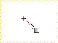
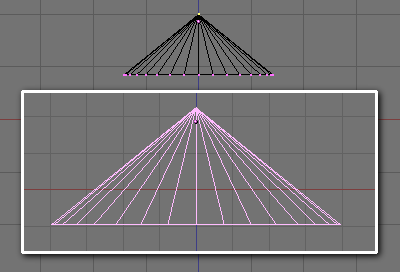
4) Maintenant utilisez l'outil dégradé pour tracer un dégradé court sur votre image, comme montré ci-dessous. L'angle du tracé va déterminer l'angle des rayures (perpendiculairement) et la longueur va déterminer la largeur des rayures.

tut_grad2

5) Voilà le résultat. Sur l'image de gauche, on voit un effet de pixelisation assez moche. Sélectionnez "Suréchantillonage adaptatif" dans les options de l'outil dégradé, et vous pourrez avoir un résultat bien plus lisse, comme à droite. :

tut_grad3 tut_grad3b

Malgré tout, ça n'est toujours pas très beau. Mais au moins, ce sont des rayures, créées simplement avec l'outil dégradé. Il suffit ensuite d'utiliser un dégradé plus adapté pour créer quelque chose l'exemple ci-dessous : (pdésolé pour les affreux artefacts de compression jpg - je crois que c'est l'hébergeur du blog qui re-sauve les images de cette façon, elles n'étaient pas si moches avant :/ )

tut_grad4

6) Vous pouvez au choix télécharger le set de dégradés près à utiliser ici stripes_gradients.zip (décompressez les et placez les fichiers .ggr dans votre répertoire  ~/.gimp-2.*/gradients/ ) ou créer vos propres dégradés (lire dessous, le point 7).

Les dégradés que je fournis dans le set utilisent les couleurs de premier et d'arrière plan, donc pas besoin de les éditer pour changer la couleur des rayures (mais vous pouvez les éditer pour changer la largeur des bandes). Ci-dessous, quelques exemples réalisés avec diverses couleurs en premier-plan/arrière-plan (et aussi différentes valeurs de "Forme" : Linéaire, Radial et Spirale) (yarrrgh, le retour de l'affreuse compression et ses artefacts)

tut_grad_examples

7) Pour créer vos propres dégradés, vous voudrez peut-être jetter un coup d'œil à cette page : http://manual.gimp.org/fr/gimp-gradient-dialog.html.

Un exemple de dégradé :

Utilisez le bouton "Créer un nouveau dégradé" au bas du dialogue de la liste des dégradés (Ctrl+G), cela va ouvrir l'éditeur de dégradés. Le dégradé par défaut est noir et blanc. 
Faites un clic-droit dessus et sélectionnez "Couper le segment en son point médiant".
Puis cliquez sur la partie gauche de la barre du bas (celle avec les triangles) afin de sélectionner le segment gauche. Faites un clic-droit et choisissez "Type de couleur gauche > Couleur de premier plan". Faites de même pour le "Type de couleur droite".
Puis sélectionnez le segment droit (clic sur la droite de la barre du bas), et faites de même pour les Type de couleur gauche et droite, mais en choisissant Couleur d'arrière plan cette fois.
Vous pouvez ensuite déplacer les triangles du bas pour changer la largeur respective des segments.

Vous avez maintenant un simple dégradé en 2 couleurs, qui peut être modifié et utiliser pour divers effets. Pour l'image qui se trouve en haut du tutoriel, j'ai simplement ajouté des rayures noires et blanches sur un nouveau calque, en mode "Superposer", de façon à ce que l'image colorée de base soit toujours visible.

Publicité
Publicité
16 septembre 2009

GIMP tutorial: Striped background

tut_grad5

This tutorial will show you how to create quickly some stripes to add to an image (for example, the image on the right here with some thin diagonal stripes)

Most tutorials depends on the use of a pattern with stripes, but here we will use gradients.
The gradient method allows to create quickly stripes of any size and any angle.

The drawback is that, even if you could use this for an illustration, it won't work as a tileable pattern (for a webpage for example). If you don't plan to do a webpage, it's ok ;)

Let's start with a quick example:
1) Create a new image (the size doesn't really matter, choose 800*600px or whatever you like, it's just an example).
2) Select any gradient you wish (even the default FG to BG).
3) Select the gradient tool. In the tool options, set "Repeat" to "Sawtooth" like show here:

tut_grad1

4) Now use the gradient tool to draw a short gradient on your image, like shown below. The angle of the "stroke" will give the angle of the stripes (x90°) and the lenght of the stroke will give the width of the stripes.

tut_grad2

5) On the left image, you can see that there's some ugly pixelation effect. Thick the "Adaptative supersampling" box in the tool options, and then you should have a much smoother result, as shown on the right image:

tut_grad3 tut_grad3b

Anyway, that still not very nice looking, right? But these are some stripes, at least :p. We just have to use a better gradient to create something like this for example: (please forgive the ugly jpeg artifacts - it looks like this blog host likes to re-save images with an awful compression :/ )

tut_grad4

6) Now you can either download this set of ready-to-use gradients stripes_gradients.zip (uncompress it and put the .ggr files inside your ~/.gimp-2.*/gradients/ directory ) or create your own gradients (read below, 7 ).

The gradients from the set use the Foreground and Background colors, so no need to edit them to change the colors (but you can edit them to change the width of some stripes). Here are some small examples with various FG/BG colors (and also different "shape" settings: linear, radial and spiral) (yarrrgh, the ugly compression strikes again)

tut_grad_examples

7) To create your own gradients to make stripes, you may want to look at this page : http://manual.gimp.org/en/gimp-gradient-dialog.html.

An example setup:

Use the "Make new gradient" button on the bottom of the gradient list dialog(Ctrl+G), it will open the gradient editor. The default gradient is a black to white one.
Right click on it and choose "Split segment at Midpoint".
Then click on the left part of the bottom bar (where there's the triangles) so the left segment is selected. Right-click and select "Left Color Type > Foreground Color". Do the same for the "Right Color Type".
Then select the right segment (click on the right of the bottom bar), and do the same for the Left and Right Color Type, but with Background Color, this time.
You can then move the bottom triangles to change the width of the left and right segments.

Now you have a simple 2-colors gradient that can be tweaked to get various effects. For the image at the top of the tutorial, I just added some black and whites stripes on a new layer, and set it to "overlay", so the colorful base image was visible.

22 février 2009

Blender Tutorial : Octopus with Subsurfs : 2/2

Last update : April 2007, for Blender 2.43 - it really needs to be updated as many things changed.

  1. Beginning the modeling
  2. Adding the subsurfs

2. Adding the subsurfs (or subdivision surfaces)

11. Using subsurf is very simple : In the Edition Menu (F9) click on "Add Modifier" (on the "Modifier" tab) and choose "Subsurf". As you can see now, a rounded shape appeared inside our mesh.

On the latest versions of blender, there is 2 different algorithms to create this subsurf (subdivision surface), "simple subdivision" or "Catmull-Clark". I think the "Catmull" one is better, so keep it selected.

You can also specify the level of subdivision displayed on the 3D view (Levels) and the one used in the render (Render Levels). The higher this level his, the better the result will be, but the more time it will take to render.
I think a level of 2 or 3 is high enough for the octopus - and in general, 2-3 is very often enough.

octopus_etape11

12. Now you only have to press the "Set Smooth" button (still on the edition menu, on the "Link and Materials" box). Then enable the shading with the Z key to see what it looks like.


(Note: If some of your tentacles look weird, this might be because you extruded some part of it without moving the points created by the extrusion, and then extruded over again. This cause some points to be superposed. To remove them, select all (A) the points, and press the "remove double" button, as on step [10.]. If some weird black mark appears, select all the points, then press Ctrl+N to recalculate the face normals.)

octopus_etape12

13. On the Shading menu (F5), click on "Add New" in the "Links and Material" tab, and define a color for your octopus in the "Material" tab, just aside. This is not supposed to be a realistic octopus, so I made mine light-blue :)

Now the octopus is almost completed, but it lacks eyes.

octopus_etape13

If you're tired - or if you don't want to add eyes to your octopus - you can stop following this tutorial here ;).

14. Switch to the object mode (Tab). On the top view(7), and on the same layer or another one -as you wish- add a sphere ( Add > Mesh > UVsphere). 20 segments and 20 rings would be Ok for this sphere.
We're going to add 2 materials to this shpere, to make the white and dark part of an eye. Go to the Editing menu (F9) and click twice on "New" to create 2 materials for this single sphere. Then, go to the material menu (F5) and click on the "2" that is displayed on the rigt of the material name. Then click on "Single User" to validate.

octopus_etape14

15. Go back to the Editing menu, and (with all the points of the sphere selected) click on "Assign" (below the "New" button). This will assign the selected material ( material #2 of "Material.001" in my example) to the whole sphere.
Then deselect all the points (A) and use the selection circle (B-B) to select the points in the middle of the sphere, as shown on the image. On the Editing menu, click on the left arrow of "2 Mat: 2" to select the other material we created. (It should now display "2 Mat: 1" ) and click once again on "Assign".

octopus_etape15

16. Go to the material menu (F5). Somewhere under the material name you should have "2 Mat 1" written. This means we're on the material #1 out of 2. And #1 is the center of the eye, so choose a dark color for it. Then click on the arrow on the right of "2 Mat 1" to get the material #2 (the white around the eye) and make it white (pretty obvious, eh?). If you press the Z key, you should now see a kind of weird eyeball in front of you.

octopus_etape16

17. Go to the side view (numpad 3), select all the points of the sphere, and press Ctrl+S to "twist" the sphere as shown on image 1. Then, press S once again, and click with the middle button (or press Z just after S) to restrain the change on size to the Z axis, and make it look as on image 2. Now if you go back to the top view, you'll see we have one funny eye.
Make it smooth (editing menu(F9) and "Set Smooth").

octopus_etape17

18. On the object mode (Tab), copy the eye (shift+D) and put the second eye just beside. Now you only have to put that great pair of eyes onto the octopus "face". I won't detail this step, with the size(S), move(G) and rotation(R) tools you should be able to do it.

octopus_etape18

19. Add a background, a few "sea objects" (pebbles, seaweeds, etc.) and that's finished ! :)

(I made the seaweeds using the same extrusion+subsurf process as for the tentacles)

octopus_etape19


----------

Creative Commons License
This work is licensed under a Creative Commons Attribution-Share Alike 3.0 Unported License.

22 février 2009

Blender Tutorial : Octopus with Subsurfs : 1/2

Last update : April 2007, for Blender 2.43 - it really needs to be updated as many things changed.

This tutorial will teach you how to make a little octopus, using the "subsurf" functionality. This functionality allows you to create smooth/organic shapes rather easily. If you don't know the subsurf function, the first part of the tutorial may seems to you very strange, because you're going to create a shape full of angles and looking like an abstract modern sculpture - instead of a smooth octopus. But then the magic of subsurf will take effect ;)
By the way, I don't have any diploma in octopus anatomy, so forgive me if that octopus looks weird. :)
This tut will also show you how to assign 2 materials to an object.

I still use the same notation as in the previous tutorials : "Press the X key to...." for a new shortcut, and only " (X) " when I use this shortcut again.

  1. Beginning the modeling
  2. Adding the subsurfs

Beginning  the modelling

1. First, on the top view (7) add a circle (space bar > add > mesh > circle).
Choose 8 vertices.

octopus_etape1

2. On the front view (1), with all the points selected, press the E key, and click on Extrude - Only Edges. Then move your cursor up to move the new points as shown on the image #1. This part is going to be the "body" of the octupus (though now it doesn't look like it).
Press the E key a second time and move the points as shown on the image #2.
Now, resize (S) the last part as in image #3.

octopus_etape2

3. Go back to the top view (7), and select (A/B) the points displayed in yellow on the image #1.
Then extrude (E, Extrude - Region) them as in #2.
(During the extrusion, the move is limited to one axis. If you want to move the vertices freely, do a single click with the middle mouse button) Extrude the points and move them some more to get something looking like what you see on image #3. This strange shape is an octopus tentacle - yeah.

octopus_etape3

4. Repeat the same process as in [3.], but with all the groups of points, so you'll get something looking like this.
Now, this might start to look like an octopus, but a very abstract one :)

octopus_etape4

5. Select (B) all the points in the middle, and go to the front view (1).

octopus_etape5

6. Press the o key (the letter "o", not "zero"). You should now see a new icon on the header.

If you click on it, you'll see a menu with the choice between different types of Falloff.
The "falloff" is the way the points that are not selected will follow the movement/size of the points that are, depending on their distance to them.

I don't think I need to explain the difference the different types, the little icons are self explanatory. Choose the Sharp falloff, for example.

octopus_etape6

7. Press the G key, but don't move the cursor. You should see a small grey circle near the selected points.

This circle tells how far the falloff influence goes.
Press the PageUp key to increase the size of that circle, until the whole octopus is within the circle. (use "Alt +" / "Alt -" or PageUp/PageDown or the mouse wheel to increase/decrease the size of the circle)
Then, move the selected points as shown on the image. You can press the "o" key again to disable the falloff mode.

octopus_etape7

8. We will now make the head of the octopus. Select (B) all the points at the top of the shape, and extrude them a little (E, Extrude - Only Edges).

octopus_etape8

9. Extrude them twice more, and resize (S) the last extrusion to make it smaller.

octopus_etape9

10. Extrude the points a last time, and then resize them to make it look as if they were only a single point.
Then, on the edition menu, on the Mesh Tools box, increase a little the "Limit" and click on "Rem Double". This will remove the points that are almost at the same place, and keep only one single point at the top of the octopus head. ("Limit" specify the maximum distance where the points/vertices would be considered a doubled).

You can also use Ctrl+M to merge the points at their center.

octopus_etape10

>> Go to the next part <<


----------

Creative Commons License
This work is licensed under a Creative Commons Attribution-Share Alike 3.0 Unported License.

22 février 2009

Tutoriel Blender: Pieuvre et Subsurf : 2/2

Dernière mise à jour : Avril 2007, pour Blender 2.43 - autant dire qu'il faut que je le remette à jour - surtout que pas mal de trucs ont changé de place depuis

  1. Début de la modélisation
  2. Ajout des subsurfs

Les SubSurfs: Surfaces de Subdivision

11. L'utilisation des subsurf est très simple : Dans le menu d'édition (F9), cliquez sur "Add Modifier" (dans l'onglet "Modifier") et choisissez "Subsurf". Vous devriez voir une forme arondie (une surface de subdivision) apparaître à l'intérieur du mesh.

Dans les dernières versions de Blender, il y a 2 algorithmes différents pour créer ces surfaces, "simple subdivision" ou "Catmull-Clark". Le "Catmull" est meilleur pour ce tutorial, alors gardez le sélectionné.

On peut également spécifier le niveau de subdivision affiché dans la vue 3D (Levels) et affiché dans le rendu (Render Levels). Plus le niveau est élevé, meilleur le résultat sera, mais ça prendra plus de temps.
En règle générale, un niveau de 2 ou 3 est très amplement suffisant.

octopus_etape11

12. Maintenant vous n'avez plus qu'a appuyer sur le bouton "Set Smooth" (toujours dans le menu d'édition - F9). Appuyez ensuite sur "Z" pour activer la vue ombrée et avoir un meilleur aperçu.

Note: si jamais certains tentacules ont l'air étrange c'est peut-être parce que vous avez extrudé une partie sans la bouger, et réextrudé par dessus. Certains points sont donc superposés et perturbent la subsurf, pour les supprimer sélectionnez tous les points (A) et cliquez sur "Rem double" comme en [10.]. Si jamais d'étranges marques noires apparaîssent, pensez aussi à "recalculer les normales" : sélectionnez tous les points, puis appuyez sur Ctrl+N.

octopus_etape12

13. Dans le menu des matériaux (F5), cliquez sur "Add New" dans l'onglet "Links and Material", et définissez une couleur pour votre poulpe dans l'onglet "Material" juste à côté. Ca n'est pas sencé être une pieuvre réaliste donc j'ai fait la mienne bleu clair :)
Maintenant la pieuvre est presque finie, il manque juste les yeux.

octopus_etape13

Si vous souffrez de flemingite aigüe ou si vous n'avez pas envie d'ajouter d'yeux, vous pouvez arrêter maintenant ce tutorial ;)

14. Passez en mode Objet (Tab).
Dans la vue de dessus (7), et sur le même calque ou sur un nouveau - comme vous voulez, ajoutez une sphère (Add>Mesh>UVSphere) de taille 20 segments et 20 anneaux.

Nous allons ajouter 2 matériaux à cette sphère pour en faire un oeil.
Allez dans le menu d'édition (F9) et cliquez 2 fois sur "New" pour créer 2 nouveaux matériaux.
Ensuite, allez dans le menu des matériaux (F5) et cliquez sur le petit "2" juste à droite du nom du matériau. Validez en cliquant sur "Single User".

octopus_etape14

15. De retour dans le menu d'édition, et avec tous les points de la sphère sélectionnés, cliquez sur "Assign" (en dessous du bouton "New"). Cela va assigner le matériau courant à la sphère.
Ensuite déselectionnez tous les points (A) puis utilisez le cercle de sélection (B-B) pour selectionner seulement les points du centre, comme sur l'image. Dans le menu d'édition, appuyez sur la flèche à gauche de "2 Mat: 2" pour sélectionner l'autre matériau. (Ca devrait afficher "2 Mat: 1") et cliquez une nouvelle fois sur "Assign". Le centre de la sphère sera maintenant de la couleur du matériau n°1.

octopus_etape15

16. Allez dans le menu des matériaux (F5). Un peu en dessus du nom du matériau il devrait y avoir "2 Mat 1" d'écrit. (On travaille donc sur le matériau 1 sur 2).
Et le matériau 1 est le centre de l'oeil, choisissez donc une couleur sombre. Cliquez ensuite sur la droite de "2 Mat 1" pour passer au matériau 2, et comme c'est le blanc de l'oeil, faites le blanc (plutôt évident,hein?). Si vous appuyez sur la touche Z, vous devriez voir une sorte de globe occulaire bizarre.

octopus_etape16

17. Allez dans la vue de côté (3). sélectionnez tous les points de la sphère, et appuyez sur Ctrl+S pour "tordre" la sphère comme sur l'image 1. Ensuite appuyez sur S, et cliquez avec le bouton du milieu ( ou bien appuyez sur Z) pour restreindre le redimensionnement à l'axe z, et que ça ressemble à l'image 2. Si vous passez en vue de dessus (1) vous verez que vous avez là un oeil cartoonesque.
Lissez le en cliquant sur "Set Smooth" dans le menu d'édition(F9).

octopus_etape17

18. En mode objet (Tab), copiez l'oeil (shift+D) et placez le 2ème oeil à coté du premier.

Il ne vous reste plus qu'a placer cette superbe paire d'yeux sur le "visage" de la pieuvre.
Je ne détaille pas cette étape, avec les outils redimensionnement (S), déplacement (G) et rotation (R) vous devriez vous en sortir.

octopus_etape18

19. Ajoutez un fond, quelques objets marins (galets, algues...) et c'est fini ! :)

(ps:j'ai fait les algues en utilisant la même combinaison extrusion + subsurf que pour les tentacules)

octopus_etape19


-----------

Creative Commons License
Ce tutoriel est sous licence Creative Commons Paternité-Partage des Conditions Initiales à l'Identique 3.0 Unported.

Publicité
Publicité
22 février 2009

Tutoriel Blender: Pieuvre et Subsurf : 1/2

Ce tutorial va vous apprendre comment créer une petite pieuvre, en utilisant la fonction "Subsurf". Cette fonctionnalité permet de créer des formes lisses/organiques assez facilement.
Ce tutorial va aussi permettre de voir comment assigner plusieurs matériaux à un même objet.

J'utilise encore la même notation que lors des tutoriaux précédents pour les raccourcis clavier : "Appuyer sur la touche X..." pour un raccourci pas encore vu, et "(X)" si on le réutilise.

Dernière mise à jour : Avril 2007, pour Blender 2.43 - autant dire qu'il faut que je le remette à jour ;)

  1. Début de la modélisation
  2. Ajout des subsurfs

Début de la modélisation

1.Dans la vue de dessus (7) ajoutez un cercle ( Barre d'espace > add > mesh > circle).
Choisissez 8 vertices.

octopus_etape1

2. Dans la vue de face (1), avec tous les points de sélectionnés, appuyez sur la touche E, et cliquez sur Extrude - Only Edges. Ensuite déplacez la souris pour bouger les nouveaux points, comme montré sur l'image 1. Cette partie est censée être le "corps" de la pieuvre (même si ça n'y ressemble pas encore).
Appuyez sur E une deuxième fois et déplacez les points comme en 2.
Maintenant redimensionnez (S) cette dernière partie comme montré en 3. (appuyez sur Z si vous souhaitez passer en mode fil de fer, pour l'affichage. )

octopus_etape2

3. Retournez dans la vue de dessus (7), et sélectionnez (A/B) les points en jaune de l'image 1. Ensuite extrudez les (E) comme dans l'image 2, mais en choisissant Extrude - Region.
(Le déplacement se retrouve contraint sur un axe, ça n'est pas bien grave. Si vous voulez déplacer en dehors de cet axe, faites un clic avec le bouton du milieu de la souris.)

Extrudez les points (toujours avec 'Extrude - Region') et déplacez les (G) encore un peu pour avoir quelque chose qui ressemble à l'image 3. Ce machin bizarre est un tentacule, si si !

octopus_etape3

4. Répetez le même procédé qu'en [3.], mais avec tous les groupes de points, pour avoir quelque chose ressemblant à cette image. Ca ressemble un peu plus à une pieuvre, mais c'est encore assez abstrait.

octopus_etape4

5. Selectionnez (B) tous les points du centre, et allez dans la vue de face (1).

octopus_etape5

6. Appuyez sur la touche o (la lettre "o", pas "zéro").

Vous devriez voir une nouvelle icone dans l'entête de la vue. Si vous cliquez dessus, vous aurez un menu avec le choix entre différents types de Falloff.
Le "falloff" est la façon dont les points qui ne sont pas sélectionnés suivent le mouvement/redimensionement des points qui le sont, selon leur éloignement.

Je ne pense pas qu'il y ait besoin d'expliquer la différence entre les différents types, les icones parlent d'elles mêmes. Choisissez le "sharp falloff" par exemple.

octopus_etape6

7. Appuyez sur G, mais sans bouger la souris. Vous devriez voir un petit cercle gris autour des points sélectionnés.
Ce cercle donne la distance d'influence du "falloff". Appuyez sur Alt+"+", ou bien utilisez la molette de la souris pour augmenter la taille du cercle jusqu'à ce qu'il inclue toute la pieuvre.

Ensuite, déplacez les points sélectionnés comme sur l'image. Vous pouvez réappuyer sur "o" pour désactiver le mode falloff.

octopus_etape7

[8.] Nous allons maintenant faire la tête de la pieuvre.
Sélectionnez (B) les points au sommet de la forme, et extrudez les un peu (E)(Extrude - Only Edges).

octopus_etape8

9. Extrudez les encore deux fois, et redimensionnez (S) les comme sur l'image.

octopus_etape9

10. Extrudez une dernière fois, et réduisez (S) la taille de façon à ce que ça ne forme plus qu'un seul point.

Dans le menu d'édition (F9), dans la boite de dialogue Mesh Tools, augmentez un peu la valeur de "Limit" et cliquez sur "Rem Double".
Cela va supprimer les points qui se superposent presque, et garder un seul et unique point au somment la tête de la pieuvre. (La "Limit" spécifie la distance max pour laquelle les points sont considérés comme superposés.)

Vous pouvez également utiliser la commande Ctrl+M pour fondre tous les points en un à leur centre.

octopus_etape10


----------

Creative Commons License
This work is licensed under a Creative Commons Attribution-Share Alike 3.0 Unported License.

22 février 2009

Blender tutorial: Winter scene : 3/3

Notice: This tutorial really needs to be updated, I'll try to do it asap.

21. Let's start with the camera. Select it, and try to point it at the snowman (with G and R), so that you can see the snowman and also the forest. You can go in the camera view (0) to help you (you can move the camera while you're in this view). The easiest way is to divide the 3Dview in 2 parts, one to display the camera view, and the other one to move the camera and see the changes.
Here I show you the place I choosed to put the camera.

hiver_etape21


22. This part is a little more difficult, because the quality of the image could change a lot depending on the lights, and there's not "magical tip" that will make the lights always looks right, in general you'll have to try many times before having something good.
Select the light/lamp (the kind of small yellow circle with a yellow dot inside that you can see on images [18.] and [19.])
Then go to the shading menu (F5) and click on "Lamp Buttons" (the square button with a lightbulb). Select "Sun" (one of the green button on the left). Then try to place it (G and R) somewhere where is would light the scene enough. (as in image [19.] for example... Don't forget to try rendering (F12) to see what it looks like).

You'll notice that the "sun" doesn't cast shadows. Only "spots" can do that [Note: this was true when I first wrote that tutorial. In the last versions of Blender, every lamp has a "Ray Shadow" that allows to cast shadows (you had to had the "Ray" button selected on the scene panel). Unselect "ray shadow" from the sun lamp if necessary]
Add another lamp (Add>Lamp), and in the same menu as before, click on "Spot", and then on "OnlyShadow", so the spot will not light the scene, only add shadows to it.

hiver_etape22

23. Try to place the spot approximately at this place with the grab (G) and rotate(R) tools. (I colored the snowman in red to show where it is) Still in the Lamp menu, tweak the values of "ClipStart" and "ClipEnd", so that the 'line' comming from the spot is tightened around the objects of the scene. (Inscrease a bit the value of ClipStart and decrease a bit the values of ClipEnd. Without that, some of the objects may have a strange shadow, or no shadow at all). You could also increase the size of the spot ("SpotSi") and its distance ("Dist").

hiver_etape23

24. Select the camera, and on the shading menu (F5) try to make the "world" color looking sky-blue.

hiver_etape24

25. On the Scene menu (F10), select "OSA" (this will enable anti-aliasing). The 5,8,11,16 buttons below set the quality of the anti-aliasing (the highest, the best). Also select the "100%" button to render the image at 100%, and then change the values of the SizeX and SizeY (this is the size of the final image). Then you'll only have to click on the big "render" button (or F12) to star the rendering.
To save your image, press F3 after the rendering.

hiver_etape25

26. Here is what it should look like :)
You'll find the Blender source of this scene in here: src/snow_scene.blend .
I added some fancy stuff on the last layer (the one on the bottom right) so you can try some renderings with the 3 layers + this one.

hiver_etape26

----------

Creative Commons License
This work is licensed under a Creative Commons Attribution-Share Alike 3.0 Unported License.

21 février 2009

Blender tutorial: Winter scene : 2/3

Notice: This tutorial really needs to be updated, I'll try to do it asap.

2. The fir trees

10. We're going to make the fir trees on a different layer than the layer of the snowman.
Layers ? Yes, the 20 little squares are the layer buttons. As far as I know, you can't have more layers, and you can't name them.
The first (and maybe the second) layers are selected, this means the snowman was created on one of them. (To select several layers, hold the Shift key when you click). If the snowman is on the 2nd layer, select it all with B (eyes and nose included) and press the "M" key. A pop-up menu appears, allowing you to choose on which layer you want to move your selection (choose the 1st layer, on the top left).
Select (only) the second layer. Switch to the top view (7), and add a Cone (Add>Mesh>Cone).

hiver_etape10

11. Switch to the front view (1), and make the cone a little flatter : select the top of the cone (right-click on it) and move (G) it. To move it only in one direction (e.g. along the z axis only) start your move in the direction you want and do a click with the middle-button. The move should now be restricted to only one axis. Click a 2nd time with the middle button if you want to cancel.
Then switch to the object mode (Tab) and increase the size (S) of the cone : make it approximately 8 squares wide.

hiver_etape11

12. Keep the cone selected, and go to the shading menu (F5). Click on Add New (as in step [9.]) and name the new material "FirTree". Then, click on the Texture Menu button.

hiver_etape12

13. Click on "Add New" to add a texture to the FirTree material, then select "Image", because the texture will be based on an image. Click on "load image" and choose the image you'll find here: tree_texture .
Set the "Xrepeat" value to 2 (the Xrepeat button is underneath the "Load image" one).

hiver_etape13

14. Go to the material menu, and select the "Map Input" tab. Then choose "Tube".
Then, make sure the cone is still selected and go back to the editing menu (F9) and select "Set Smooth" (as in step [7.]).
By the way, the textures can't be seen in the solid mode (Z), they're visible only in the renders. (the only textures visibles in the 3D views are the UV-mapped textures, but I'm not going to explain them in this tutorial ;) )

hiver_etape14

15. In the front view (1), duplicate (Shift+D) the cone, and put the duplicated cone above the other. Repeat this once to have 3 cones. Decrease a little the size of the cone on the top and on the middle. You should have something looking like in the picture.

hiver_etape15

16. Switch to the top view (7) and add a cylinder (Add>Mesh>Cylinder). Make it small enough (S) to be the trunk of the tree, and put it at the right place in the front (1) view.
Repeat the same things as in steps [7.] and [8.],( or step [9.]) to make it smooth and add a material to it. Make the material brown (approximately R:0.500 - G:0.250 - B:0.000).

hiver_etape16

17. Switch to the top view and select the whole fir tree (A - or B and draw a square around it) . Then, select the first layer (press Shift when you click on it to keep the layer with the fir tree selected.) There's a great probability that the fir tree will be over the snowman, so move it (G) beside.

hiver_etape17

18. Use Shift+D to copy the fir tree and create a little forest around the snowman. (Don't put fir trees in front of him, or he'll be totaly hidden from the camera). You can make some trees bigger or smaller, so it won't look to artificial (yes, I know, trees made out of 3 cones and a cylinder *do* look artificial, but let me dream it's not the case ;) ). Make sure (in the front/side view (1/3)) that the bigger trees are not half-underground and the smaller trees half-flying.

hiver_etape18

19. Go on another layer and add a plane (Add>Mesh>Plane). Now select the 3 layers you used, and (with the plane still selected) grow the plane to be bigger than the forest. This is going to be the ground.
Switch to the object mode (Tab) and make sure it the front or side view (1 or 3) that the ground is not floating above the tree, but under them.

hiver_etape19

20. Now go to the shading menu (F5), and instead of choosing "Add New", click on the small arrows on the left of the AddNew button and choose "Snow".

hiver_etape20


>> Go to Next part <<

----------

Creative Commons License
This work is licensed under a Creative Commons Attribution-Share Alike 3.0 Unported License.

21 février 2009

Blender tutorial: Winter scene : 1/3

Notice: This tutorial really needs to be updated, I'll try to do it asap.

This tutorial will tell you how to make a simple winter scene. Some fir trees and a snowman. It is supposed to show you how to use the most common Blender fonctionnalities (modeling, adding materials and textures) and shortcuts. When a shortcut is used for the first time, I'll say something like "press the x key". When I use it again, I'll just put something like "(x)".

The Snowman

1. If there's a squarePress the X key to delete the square  that is in the middle of the scene. Press the space bar. Select Add > Mesh > UVSphere to add a sphere in the scene (click on the OK button for the number of segments and rings, 32 is perfect). Zoom in ("+" key or the scroll button on the mouse) and press the S key (size) to make the sphere 4 squares wide. (if you want it to be excactly 4 square wide, hold the Ctrl key while you move the mouse ).
This is going to be the body of the snowman.

hiver_etape1

2. Press the Tab key to switch to the oject mode. (the sphere is now displayed in pink). On the bottom of the 3D view, there's a little menu with icons, click on the one circled in red (or press F9), and change the values of the 2 fields with a name that fits (e.g. SnowmanBody). It is not necessary to name the object, but that's a good habit to have :)

hiver_etape2

3. Add a 2nd UVsphere in the scene, and then switch to the front view (numpad 1). Resize (S) the sphere to 2 squares wide. Switch again to the object mode (Tab) (when you create and object, Blender automatically switch to the Edit Mode). Name it SnowmanHead (as done in the previous stage).
Now press the G key (G=Grab) and move the head on top of the body.
You should have something looking like this. This is the beginning of the snowman. (You can add him some "arms" if you want, or a 2nd snowball for the body). If you're satisfied with the shape of your snowman, you can "link/join" all the elements together. Select them by pressing the B key and drawing a square all around them. Then press Ctrl+J and click on "join selected meshes".

hiver_etape3

4. Now, let's create his face. Stay in the front view, press the space bar and choose Add > Mesh > Cone. Switch to the side view (3 on numpad). The cone is going to be the nose, and as you can see, it's much too big. Deselect all the points by pressing the A key. Then select only the points on the right (the base of the cone)(B). Press the S key and decrease the size of the base of the cone. Switch to the object mode(Tab), and press the S key to decrease the size of the "nose" of the snowman.  Then put the nose (G) of the face of the snowman.

note : the other sphere you can see is only an arm I added to the snowman

hiver_etape4

5. Switch to the front view (1 on numpad), add a sphere, and make it small enough (S) to be one of the eyes of the snowman. Press Tab to be on the object mode, and put (G) your sphere at the place of one eye. Then, with this sphere still selected, duplicate it by pressing Shift+D, and put it (G) at the place of the second eye.

Zoom in (+) and select the 2 eyes ( right-click on the first one if it's not already selected, and Shift+right click to select the other one. They should now appear in 2 different tints of pink. Be sure to be close enough not to select the snowman instead of the eyes. (If it happens, press the A key to deselect all and try again, or press the B key and use the middle mouse button to draw a square around what you want to deselect.) Now, join the 2 eyes (Ctrl+J).

hiver_etape5

6. Keep the eyes selected, and go on the top view (7 on numpad), and move the eyes as shown in the picture. To be sure they're visible, press the Z key to switch to the "Solid" mode (instead if the "wireframe" mode), and move around the snowman (hold the middle mouse button down, and move the mouse). As you can see, the snowman is all grey. We're going to make it look better. Press Z once again to switch back to the wireframe mode.

hiver_etape6

7. In the object mode (tab) select the snowman body.Now go to the editing menu (F9 or the button that is circled) and click on "Set Smooth". If you press Z now, the snowman should look smoother. Then, click on "New" to create a new material for the snowman, and on "Shading" (or F5) to go on the shading menu.

hiver_etape7

8. Name the material "Snow", and change the R,G,B values to 1, to get a white color, and also set the "Hard" value to 1 (If it's bigger than 1, you'll get a grey snowman looking more like metal than snow) and the specularity value to approximately 0.15, and the "Ref" value to 1.

If you go on the solid mode (Z) once again, you'll see almost no changes. They'll be noticable only if you make a render of the scene. (This is the F12 key. If you see nothing, don't panic, that only that your camera is not "watching" your snowman. Select the camera (the triangular stuff that should be hidden somewhere in the scene - If you deleted it before, press the bar and choose Add>Camera) and use the rotation ( R) and move (G) to point it at the snowman. Press the 0 key (zero in numpad, not "o") to be in the "camera view" and check that you can see the snowman, and try to render the scene again.)

hiver_etape8

9. Now, select the nose of the snowman. On the shading menu (F5) click on "Add New" to create a new material for this part. Name it "Orange" or whatever you want, and set the RGB values to get something orange.

There's a big probability that the nose still looks very dark if you make a render (F12). You could change the "Ref" value to 1, and tweak the "Spec" and "hard" values if you want. But the fact that it looks dark is mostly a light problem, and we'll fix the light later.

Do the same thing for the eyes of the snowman ( name the material "coal" for example, and set the RGB values to zero).

hiver_etape9


>> Go to Next Part <<

----------

Creative Commons License
This work is licensed under a Creative Commons Attribution-Share Alike 3.0 Unported License.

21 février 2009

Tutoriel Blender : Scène hivernale : 3/3 (Vieux)

Note : Ce tuto a été mis à jour pour la dernière fois en janvier 2008, il ne correspond plus vraiment à la version actuelle de Blender. (Sachant que depuis la version 2.50, l'interface de Blender a *énormément* changé.)


La caméra et l'éclairage

21. Commençons par la caméra. Sélectionnez la, et essayez de la pointer vers le bonhomme de neige (avec G et R), de façon à ce qu'on voit également la forêt. Vous pouvez passer en vue caméra (0) pour vous aider. (On peut également bouger la caméra qd on est dans cette vue).
Le plus pratique est de séparer la vue 3D en 2, et d'afficher la vue caméra dans une des parties, et de regler la caméra dans l'autre.

L'image montre où j'ai placé la caméra (mais vous pouvez choisir un autre angle).

hiver_etape21

22. Cette partie est un peu plus difficile, car la qualité de l'image peu beaucoup changer selon les lumières, et celles ci ne sont pas faciles à regler. Il n'y a pas d'astuce magique qui face que ça marche à tous les coups, en général il faut pas mal d'essais pour avoir quelque chose de correct.

Séléctionnez la lumière (l'espèce de cercle jaune avec un point jaune au milieu qu'on peut voir sur les images [18.] et [19.] - un point noir avec un cercle, a partir de la version 2.40)
Ensuite passez au menu d'ombrage (F5) et cliquez sur "Lamp Buttons" (le bouton carré avec une ampoule). Sélectionnez "Sun" (un des boutons verts sur la gauche). Ensuite essayez de placer (avec R et G) la lampe à un endroit ou elle éclaire bien la scène. (Comme sur l'image [19.] par exemple... n'oubliez pas de faire des rendus (F12) pour savoir ce que ça donne). Cette lumière servira d'éclairage d'ambiance.

On remarque que le "soleil" ne projete pas d'ombres. Seuls les spots le font [Note: ceci était vrai au moment où j'ai écrit ce tutorial pour la première fois, dans les versions récentes de Blender, toutes les lampes disposent d'un bouton "Ray Shadow" qui leur permet de projetter des ombres (il faut avoir le bouton "Ray" également activé dans le menu de rendu de la scène). Déselectionner le "ray shadow" de la lampe "sun" si nécéssaire]
Ajoutez une autre lampe (Add>Lamp), et dans le même menu, cliquez sur "Spot" au lieu de "Sun", puis sur "OnlyShadow" , comme ça le spot ne rajoutera pas de la luminosité à la scène, seulement des ombres.

hiver_etape22

23. Essayez de placer le spot environ comme sur l'image avec G et R. (J'ai colorié le bonhomme de neige en rouge pour qu'on voit où il se situe).
Toujours dans le menu Lamp, reglez les valeurs de ClipStart et ClipEnd de manière à ce que le trait continu qui part du spot soit plus "resserré" autour des éléments de la scène. (Augmentez un peu les valeurs de clipstart et diminuez un peu celles de clipEnd. Sans ça, il se peut que certains de vos objets aient une ombre bizarre ou pas d'ombre du tout).
Vous pouvez également augmenter la taille du spot ("SpotSi", pour "spot size"), et sa distance d'éclairage ("Dist").

hiver_etape23

24. Sélectionnez la caméra, et dans le menu Shading (F5), essayez de faire que le monde ("world") soit bleu ciel.

hiver_etape24

25. Dans le menu de Scène (F10), sélectionnez "OSA" (ça active l'anti-aliasing). Les valeurs 5,8,11,16 en dessous spécifient la qualité de l'anti-aliasing. Sélectionnez aussi le bouton "100%" pour que le rendu soit en taille réelle, et ensuite changez les valeurs de SizeX et SizeY (ça sera la taille de l'image rendue).
Ensuite il ne reste plus qu'a cliquer sur le gros bouton "Render" (ou F12) pour lancer le rendu.
Pour sauvegarder l'image rendue, appuyez sur F3.

hiver_etape25

26. Voilà à quoi ça devrait ressembler :)
J'ai ajouté quelques trucs sur le dernier calque (celui le plus en bas à droite) donc vous pouvez aussi essayer de faire des rendus avec ce calque activé en plus des autres.

hiver_etape26


-----------

Creative Commons License
Ce tutoriel est sous licence Creative Commons Paternité-Partage des Conditions Initiales à l'Identique 3.0 Unported.

Publicité
Publicité
1 2 > >>
Open Tuts
Publicité
Archives
Publicité